What is an electrical contactor?
To put it simply, a contactor is a device with the ability to allow / cut the flow of the electrical current to a receiver with the possibility of being remotely operated.
The job of a contactor
Among its most common applications are starting and control of electric motors, energization of resistive loads, capacitor bank, lighting systems, among many others.
Fun fact: The contactor is the most used element in the operation of motors and other power devices.
The dimensioning of the contactor is done by matching the current of load to be controlled, under established conditions of use, for a given temperature, with the kind of current that passes through the power circuit and the one used for the coil.
The contactors have two operating positions:
- A stable or resting one, when it does not receive any action from the control circuit.
- An unstable one, when said action acts.
This type of operation is often called “all or nothing.”
Types of Contactors
These are some of the different types of contactors:
- Electromechanical contactors. They are actuated with the help of mechanical means.
- Electromagnetic contactors. Its actuation is carried out through an electromagnet.
- Hydraulic contactors. They are activated by the pressure of a liquid.
- Pneumatic contactors. They are activated by the pressure of a gas.
Composition of an Electromagnetic Contactor
An electromagnetic contactor is composed of the following parts:
- Main contacts: They are intended to open and close the power circuit. They are open at rest.
- Auxiliary contacts: They oversee opening and closing the control circuit. They are mechanically coupled to the main contacts and can be open or closed.
- Coil: Element that produces an attractive force (AF) when crossed by an electric current. Its supply voltage can be 12, 24 and 220V alternating current.
- Armor: Moving part of the contactor. It displaces the main and auxiliary contacts by the action (AF) of the coil.
- Nucleus: Fixed part by which the magnetic flux produced by the coil is closed.
- Spring: In charge of returning the contacts to their rest position once the AF force ceases.
How does a Contactor work?
The circuit to be controlled is connected to the main contacts. Ensuring the flow / cut of the main current and according to the number of current pathways, it could be bipolar, tripolar, tetrapolar, etc. performing the maneuvers simultaneously on all tracks.
Auxiliary contacts are of two classes open and closed. These are part of the auxiliary circuit of the contactor and ensure the self-powering, the commands, contact interlocks and signals in the automation equipment.
When the contactor coil is excited by the circulation of current, it moves the core inside and drags the main and auxiliary contactors, establishing the circuit between the network and the receiver through the poles.
This drag or shift can be:
- By rotation, it pivots on its axis.
- By translation, sliding parallel to the fixed parts.
- Combination of movements, rotation, and translation.
When the coil stops being fed, it opens the contacts by the effect of the pressure spring of the poles and the return spring of the movable armature.
The coil is designed to withstand the mechanical shocks caused by the closing and opening of the contacts and the electromagnetic shocks due to the passage of current through its turns. The two are sometimes mounted on shock absorbers to reduce mechanical shocks to the coil or magnetic circuit.
If it is necessary to control from different points, the start buttons are connected in parallel and the stop button in series.
Terminal symbols and referencing
The connection terminals of the contactors are named by figures or codes of figures and letters that allow their identification, facilitating the creation of diagrams and wiring work.
- The main contacts are referenced with a single number, from 1 to 16.
- Auxiliary contacts are referenced with two figures. The unit figures or function figures indicate the function of the contact:
- 1 and 2, normally closed contact (NC).
- 3 and 4, normally open contact (NO).
- 5 and 6, timed opening contact.
- 7 and 8, timed closing contact.
- The tens figure indicates the serial number of each contact in the contactor. On one side it is indicated which contactor it belongs to.
- The coils of a contactor are referenced by the letters A1 and A2. At the bottom it is indicated which contactor it belongs to.
- The contactor is named with the letters KM followed by a serial number.
Contactor Applications
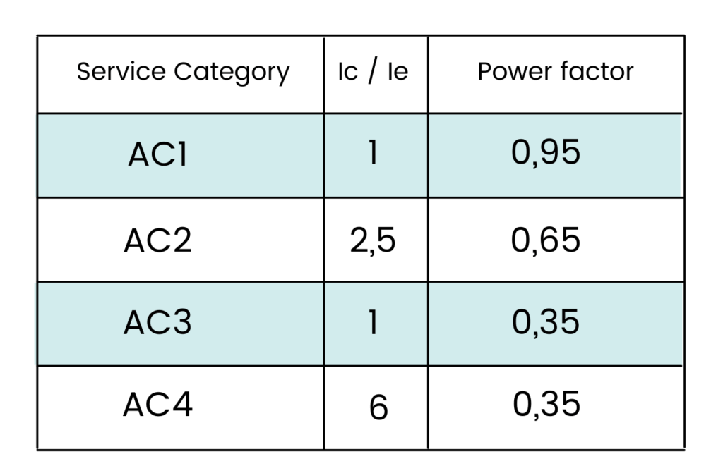
Depending on the service category, the contactor applications are:
Service Category | Applications
AC1 | Purely resistive loads for electric heating, …
AC2 | Asynchronous motors for mixers, centrifuges, …
AC3 | Asynchronous motors for air conditioners, compressors, fans..
AC4 | Asynchronous motors for cranes, elevators, …
• The nature and use of the receiver, that is, its category of service.
• The cut-off current, which depends on the type of service category and is obtained from the service current, amps (A).
Choosing a Contactor – Example
Choose the most suitable contactor for an electric heating circuit, made up of weakly induced resistors, whose characteristics are as follows:
- Nominal voltage: 220V
- Total potential: 11 kW
- Power factor: 0.95 inductive.
Solution:
1. The service current is obtained by applying the expression of the power in a three-phase circuit: Ic = P / (√ 3 * V * cos φ) = 30.5A
2. The category is AC1, as the receiver is resistive and its power factor ( cos φ) is close to unity.
3. The cut current is equal to the service, so the size of the contactor to choose is 32A.
The categories of the chosen contactor are:
• Category: AC1 (since cos φ = 0.95).
• Caliber: 32A.
Choosing an Electromagnetic Contactor
It is necessary to know the following characteristics of the receiver:
• The nominal operating voltage, in volts (V).
• The operating current (Ie) it consumes, in amperes (A).
Mechanical power (Pm) (kW)
Following steps for choosing a contactor:
1. Obtain the operating current (Ie) consumed by the receiver.
2. From the type of receiver, obtain the category of service.
3. From the chosen service category, obtain the cut-off current (Ic) with which the meter gauge will be obtained.
In addition, the condition of the power factor must be considered, since, in the case of lighting circuits with discharge lamps (mercury vapor, sodium, …) with a power factor of 0.5 (without compensating), its category service is AC3, although by its nature it should be AC1. Whereas if it were offset at 0.95, its category would be AC1.
Here at ICA, we have an extensive stock of contactors from top brands such as Schneider Electric at competitive prices! If you can’t find the model you are looking for, please contact us and we will find it for you!